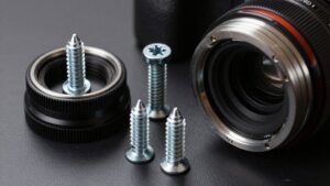
1/4-20 Vs 3/8-16 Tripod Threads: Which Screw Size Fits Your Gear?
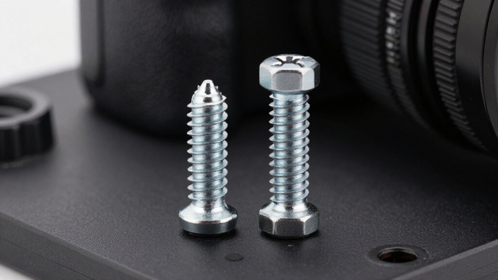
Your tripod gear’s threaded socket determines whether you need a 1/4-20 UNC or 3/8-16 UNC screw.
Both are coarse threads, but they aren’t interchangeable: 1/4-20 measures 1/4-inch diameter with 20 TPI, while 3/8-16 measures 3/8-inch diameter with 16 TPI.
Inverting a mount doesn’t change its thread size. Start the screw by hand, make sure it engages fully without bottoming out, then tighten until snug.
Confirm fitment and load requirements before adding adapters; the details below help you secure your setup safely in use.
UNC Diameter and Pitch Reference
Although tripod threads use familiar imperial labels, the numbers describe diameter in inches: 1/4-20 UNC has a 1/4-inch (6.35 mm) major diameter and 20 threads per inch (TPI), while 3/8-16 UNC has a 3/8-inch (7.94 mm) diameter and 16 TPI.
| Thread | Reference |
|---|---|
| 1/4-20 UNC | Diameter: 1/4 inch (6.35 mm) |
| 1/4-20 UNC | Pitch: 20 TPI |
| 3/8-16 UNC | Diameter: 3/8 inch (7.94 mm) |
| 3/8-16 UNC | Pitch: 16 TPI |
| UNC | Unified coarse thread designation |
Use the diameter and TPI together when checking your camera, plate, or head. UNC identifies the unified coarse thread form; it doesn’t make the two sizes interchangeable. A 1/4-20 screw won’t match a 3/8-16 receiver because both its diameter and thread count differ. Confirm the stated size before choosing a screw or adapter; don’t infer compatibility from appearance alone for your setup.
Thread Engagement Depth
Thread engagement depth is the length of screw that actually enters the camera or head’s threaded insert, and it determines how the load is shared. Check this depth when comparing 1/4-20 and 3/8-16 mounts. The 1/4-20 thread has 20 threads per inch, so you need sufficient engagement to limit local pressure and reduce stripping risk, particularly under dynamic loads.
A 3/8-16 thread has fewer threads per inch, but don’t assume the larger diameter makes every setup safe.
Adapters, especially thin reducing bushings, can leave too little effective engagement and concentrate force on fewer thread surfaces. Receiving depth also varies between camera bodies; reported differences reach about 25%, so identical thread sizes may need different plate screw lengths. Choose a screw that engages fully without bottoming out, and avoid spacers that shorten engagement.
Vibration Resistance in Practice
Engagement depth sets the available contact area, but panning, tilting, and wind gusts add dynamic loads that can loosen a connection or strip its threads. Even when your screw feels secure at rest, repeated motion works the thread flanks and raises shear stress, so a small 1/4-20 interface can fail sooner than a 3/8-16 connection with greater engagement area.
P = F/A: when vibration reduces effective contact area, pressure rises; a low-quality bushing can concentrate load until thread shear strength is exceeded.
Your rig’s torque follows τ = m·g·L, so a setup or off-axis accessory increases rotational strain that motion can amplify. Choose a native 3/8-16 mount when your head and camera support it; avoiding a down-sizing bushing keeps vibration loads off adapter threads.
Tool-Free Hand Tightening
For either a 1/4-20 or 3/8-16 tripod mount, start the screw by hand to catch the threads cleanly, then tighten until fully seated and snug; no tool needed. Use the correct thread size; don’t force a mismatch, which can load the first engaged threads and raise stripping risk. Stop when the connection seats; extra torque won’t improve security and can damage threads.
If a stiff HDMI cable pulls near the plate, route it and relieve strain before mounting, since cable torque can loosen the hand-tightened connection over time. Finish with a light tug test to check for movement; don’t yank. Confirm the rig stays fixed, rather than trusting its weight alone. This check helps catch a loose mount without adding tools or stressing the threads.
Lens Collar Mounting Differences
When mounting a lens collar to a plate, match the screw to the collar’s specification: 1/4-20 UNC is common on lighter gear, while 3/8-16 UNC is often used on heavier setups. Check the stamped specification before choosing a plate or adapter. The sizes aren’t interchangeable: 1/4-20 has a 1/4-inch major diameter and 20 threads per inch; 3/8-16 has a 3/8-inch diameter and 16 threads per inch.
If your collar accepts both, choose 3/8-16 for greater clamping capacity on a larger rig. Don’t adapt a 3/8-16 collar to a 1/4-20 head, or the reverse; a reducing bushing can concentrate load on fewer threads as you pan or tilt. Use the matching screw, and check that plate and collar geometry allow adequate engagement.
A screw that’s too short or blocked before seating can loosen or fail under load. This matters when your rig carries a heavy lens and moves during tracking or repositioning with substantial tilt and pan.
Replacement Screw Availability
Replacement screws for tripod and quick-release systems usually come in the common UNC sizes: 1/4-20 (20 TPI, about 6.35 mm) and 3/8-16 (16 TPI, about 7.94 mm). Choose the thread that matches your gear’s female socket; 3/8-16 screws appear more often on pro heads and heavier plates, while 1/4-20 replacements suit smaller mounts and accessories.
When ordering, verify screw length as well as diameter and pitch: cameras differ in receiving depth, even when they share a plate standard. An overly long screw may bottom out, while a short one may not provide adequate engagement. If your rig uses a reducing adapter, check engagement length carefully because the adapter narrows the contact area and concentrates load.
Use the manufacturer’s recommended length when you’re unsure; don’t substitute a generic screw without checking the camera’s specified receiving depth. You can find replacements from camera shops and plate manufacturers; confirm specifications before buying.
Cross-Threading Under Pressure
If you force a 1/4-20 screw into a 3/8-16 thread, or the reverse, at an angle, the mismatched pitches can cam over, leaving only a few threads engaged. Because 1/4-20 has 20 TPI and 3/8-16 has 16, their threads won’t match; forced contact creates localized pressure, deformation, and rapid stripping risk.
Movement makes the hazard worse: panning, tilting, vibration, or gusts can turn poor alignment and looseness into connection failure. An adapter won’t correct a crooked start; it can focus stress on a thin aluminum bushing and mismatched threads. Use this simple check:
- Start screw by hand with light finger torque; feel smooth entry.
- Stop if it feels gritty or tight early; don’t force it.
- Apply tightening torque only after threads run smoothly without binding.
Clamp-Load Distribution
When you choose a 3/8-16 thread over 1/4-20, its larger contact area spreads clamp load and lowers local pressure. Since pressure equals force divided by area, full engagement with the correct thread helps reduce stripping under vibration.
Avoid reducing adapters when possible, as they concentrate load on fewer threads.
Contact Surface Area
At the threads, a 3/8-16 mount offers a larger effective contact area than a 1/4-20 mount, helping spread the same clamp force and reduce local pressure. Because pressure equals force divided by area (P=F/A), less engaged surface raises stress at the threads.
A 3/8-16’s 0.375-inch major diameter and 16-TPI form typically provide more engagement area than a 1/4-20’s 0.250-inch diameter and 20-TPI form, when both engage properly. Shallow engagement or a thin adapter can leave fewer contact surfaces carrying the load, increasing stripping risk, especially under dynamic use.
- Check the specified engagement depth; diameter alone won’t ensure adequate thread contact.
- Avoid adapters that reduce thread bite unless their design preserves full engagement.
- For heads, use the 3/8-16 interface to limit stress per unit area.
Even Pressure Distribution
Even clamp-load distribution depends on full thread engagement, not diameter alone. When you match the mount and camera threads—1/4-20 UNC or 3/8-16 UNC—you engage more of the available thread depth and spread tightening force across more contact area.
A properly mated 3/8-16 joint generally distributes pressure more evenly than a marginal 1/4-20 fit at similar torque. If load lands on fewer thread turns, local pressure rises (P = F/A) and can exceed thread shear strength, damaging the mount or screw. Thin reducing bushings can shrink effective engagement area, even when thread pitch seems compatible, and worsen that concentration. Choose direct compatibility in both diameter and pitch to distribute clamping force across engaged threads; don’t rely on a bushing to correct a mismatch safely.
Inverted Tripod Mount Compatibility
Inverting your tripod mount doesn’t change the thread standard: match the male and female geometry, typically 1/4-20 or 3/8-16 UNC. Check that the screw engages deeply enough without bottoming out, and confirm the lock secures the mount.
Avoid reducing bushings where possible; before shooting, verify the lock indicator and perform a tug test.
Thread Orientation Basics
Mount orientation doesn’t change thread size: camera and tripod fittings typically use coarse UNC threads, most often 1/4-20 or 3/8-16. Inverting a plate changes the direction of assembly, not its diameter or pitch. Match the same male or female interface, and don’t treat 1/4-20 and 3/8-16 as interchangeable; a screw may seem to start before binding. With an inverted mount, check engagement depth: the screw can bottom out sooner, so don’t force it.
- Match diameter and pitch, not merely apparent thread entry; unlike sizes can bind and damage fittings.
- Choose adapter gender for the receiving interface; male-to-male works only with intended external-thread interfaces.
- Lock the assembly and use a gentle pull test, since inversion increases leverage and can reveal partial engagement in your next field session.
Checking Mount Compatibility
Before buying an inverted-mount accessory, check whether your camera has a 1/4-20 or 3/8-16 thread; these sizes aren’t safely interchangeable. Identify the female receiving thread on the inverted plate or head, too; the camera-side specification alone doesn’t confirm that the mount matches. Check the screw’s length against the available engagement depth.
The screw must engage sufficiently without bottoming out before the mounting surfaces meet.
Start it by hand and turn gently. It should run smoothly; if it binds quickly, stop rather than forcing it, since mismatched UNC threads can damage either component. Choose a direct size match whenever possible, and account for the orientation change when you inspect the connection. Confirm the camera and mount share a thread standard and intended engagement depth beforehand.
Adapter Fit and Security
For an inverted setup, use the camera’s native thread whenever possible: 3/8-16 UNC generally clamps more securely than 1/4-20 UNC under the higher leverage of tilting. Avoid cheap reducing adapters; adapting 3/8-16 down to 1/4-20 reduces engagement and concentrates load on the smaller bushing surface.
- Match thread size and geometry: check the camera’s female receiving depth against the plate screw length; dimensions can vary about 25% between models.
- Tighten until the indicator clicks, then perform a firm tug test to confirm engagement before panning or tilting.
- Route cables to remove strain torque; a stiff HDMI lead can loosen plate screws over time, especially when inverted.
Recheck the connection during use. Dynamic movement can loosen a marginal fit and strip threads under repeated load cycles.
Verify Manufacturer Specifications
Specification checks prevent mismatched screws and shallow engagement. Before mounting, inspect your camera body and quick-release plate for the UNC thread: 1/4-20, with a 1/4-inch diameter and 20 TPI, or 3/8-16, with a 3/8-inch diameter and 16 TPI.
Confirm the female thread engagement depth; ISO 1222 doesn’t establish a receiving depth that guarantees screw compatibility. Check the manufacturer’s receiving or latching depth, or required screw length, especially when switching between thread systems.
Don’t rely on thin reducing bushings that seem to fit: they reduce engagement area and concentrate load on contact area, increasing failure risk.
When pairing Arca plates with camera mounts, match the plate screw length to your camera’s receiving depth; don’t assume models match.
Conclusion
Choose 1/4-20 for most camera bodies, plates, and compact accessories; use 3/8-16 when your head, collar, or support specifies the larger connection. Match diameter and pitch exactly, and don’t force a screw that binds. Check engagement depth, clamp load, and clearance before tightening, especially under vibration or when mounting inverted.
If you’re unsure, verify the manufacturer’s specification and use the supplied adapter. The correct thread protects your gear and keeps the assembly secure in use.