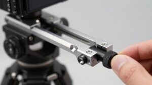
Tripod Mount Thread Size Chart: Cameras, Heads, Lights and Accessories
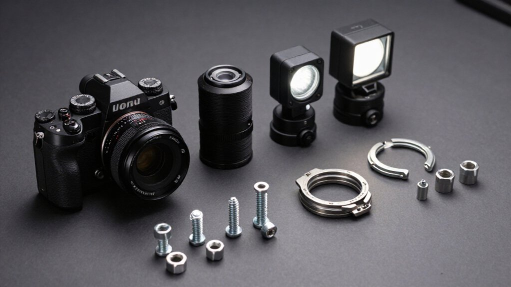
You can identify most tripod and accessory mounts by matching their male screw to the female socket: cameras and quick-release plates commonly use 1/4-20 UNC, while tripod heads and heavier interfaces often use 3/8-16 UNC.
The numbers mean 1/4-inch or 3/8-inch major diameter and 20 or 16 threads per inch.
Don’t force a mismatch; use the correct adapter.
Check engagement depth so the screw clamps securely without bottoming out.
The chart below helps you verify fit.
1/4-20 Versus 3/8-16
On a tripod mount, 1/4-20 and 3/8-16 identify two different UNC thread sizes: 1/4-20 is the common camera-body and quick-release-plate thread, while 3/8-16 is larger and often used on tripod heads and heavier interfaces.
When you choose a connection, match the screw to the threaded socket rather than forcing engagement. The sizes differ in both diameter: 0.25 versus 0.375 inch, and pitch: 20 versus 16 threads per inch, so a metric screw won’t fit either UNC thread.
You’ll commonly find 1/4-20 beneath consumer cameras and in plate screws; it suits lighter setups. A 3/8-16 connection offers greater stiffness for heavier cameras and lenses, particularly between the head and legs.
Before selecting hardware, inspect a 3/8-16 head for an installed reducer bushing; that insert may let you use a 1/4-20 screw. If not, use the correctly sized screw or adapter. Never force a mismatched thread, which can damage the socket. Check each interface carefully before packing your support system.
Camera Gear Thread Compatibility Chart
To confirm camera gear thread compatibility, align the UNC size at every connection: most camera bodies and quick-release plates use a male or female 1/4-20 thread, while tripod head bases often use 3/8-16.
| Gear | Common thread | Check |
|---|---|---|
| Camera/plate | 1/4-20 | Male screw to female mount |
| Head base | 3/8-16 | Match support connection |
| Adapter | 3/8-16 to 1/4-20 | Verify fit |
Before you attach gear, identify both sides: a female 1/4-20 plate needs a matching male screw, while a head may present 3/8-16. Match UNC standards; metric threads won’t fit. If sizes differ, use a bushing, commonly converting a 3/8-16 head to accept a 1/4-20 plate screw. Ensure full engagement without bottoming out; early tightening can leave the mount unclamped and risk damage to your gear.
Major and Minor Diameters
The “1/4” and “3/8” in UNC tripod thread sizes name the nominal major diameter: 0.25 inch for 1/4-20 and 0.375 inch for 3/8-16. On a screw, this is the outside measurement across the thread crests; in a socket, the minor diameter lies at the thread roots and is smaller.
These dimensions describe different surfaces, so don’t compare a screw’s major diameter directly with a socket’s opening as if they were identical measurements. For a dependable mount, check that the male thread’s major diameter suits the female thread’s acceptance geometry. If the sizes don’t correspond, the screw may wobble, bind, or fail to seat securely.
Use your chart or the component specification before pairing a camera, head, light, or adapter. Don’t assume similar-looking metric hardware fits; check before you install it.
Pitch and Engagement Depth
Thread pitch sets how far your screw advances per turn: 1/4-20 advances 1/20 inch, while 3/8-16 advances 1/16 inch. Check the mount’s usable thread depth so the screw engages fully without bottoming out before it clamps.
A screw that’s too short may loosen under load, while one that’s too long may feel tight without securing the plate.
Thread Pitch Basics
On tripod mounts, UNC pitch is the axial distance between thread crests: 1/4-20 has 20 threads per inch, spaced more tightly than 3/8-16’s 16.
That spacing describes how the threads advance along the screw; it doesn’t tell you how securely an accessory will seat. Engagement depth is the length of screw thread that actually overlaps the camera’s or head’s female thread.
You’ll get a more dependable clamp when enough thread engages to resist movement. With too little overlap, friction can make the connection feel tight at first, yet vibration may loosen it.
If your screw exceeds the receiving depth, it can bottom out before the accessory clamps against its surface. You may feel resistance and mistake it for a secure fit. Check screw length against available thread depth, then tighten until the mating faces contact without forcing the mount. Recheck the joint after use where vibration is expected.
Standard UNC Pitch
Because tripod mounts use coarse UNC threads, 1/4-20 has 20 threads per inch and 3/8-16 has 16, so their spacing—and the number of turns needed to clamp—differs. Match the pitch as well as the diameter: a screw with the wrong spacing won’t mate correctly, even when its nominal size appears right. The finer spacing of 1/4-20 advances less per turn than 3/8-16, so you may need more turns to achieve clamping.
Check screw length against the receiving hole’s threaded depth when you mix plates, heads, lights, or accessories. The screw must enter far enough for the mount to tighten, but it must not reach the hole’s base first. If it bottoms out, it can feel tight while the plate or head remains loose.
Usable Thread Engagement
Matching pitch sets how far the screw advances per turn—1/20 inch for 1/4-20 and 1/16 inch for 3/8-16—but usable engagement depends on the receiving hole’s depth.
Usable engagement is the length of screw thread captured by matching female threads in your camera, head, plate, or accessory. A screw that bottoms before clamping can feel tight while providing little thread grip. Choose a length that gives several millimeters of engagement, at least a few full threads, without exceeding the receiving thread’s usable depth. Because 3/8-16 advances farther per turn than 1/4-20, equal turn counts don’t mean equal insertion distances. Match diameter and pitch so the screw engages the mating threads securely and can clamp the components together.
Check Mounting Depth
Before checking depth, confirm the thread pitch: 1/4-20 UNC has 20 TPI, while 3/8-16 UNC has 16 TPI. Mismatched threads won’t seat correctly. Measure or check the female threaded depth in your camera or head, then compare it with the screw’s usable threaded length.
The screw should turn freely through that depth and reach full engagement before you tighten the plate or clamp. Confirm the accessory sits flush and doesn’t bind as you start the screw by hand. Choose a screw whose length and pitch provide adequate threaded grip within the mount; proper engagement lets the clamp hold securely.
If resistance appears early, stop and recheck pitch, screw alignment, and available depth rather than forcing the connection. Test the fit without tools first.
Avoid Bottoming Out
A screw can feel tight before it secures the accessory if it bottoms out against the base of the threaded hole. The screw stops before it pulls the clamp or accessory down, so the mount may loosen during use. Test-fit the screw before tightening: it should turn freely through the threads, not stop immediately. Choose a length that gives you enough engagement turns without contacting the hole’s bottom.
Thread pitch determines how turns relate to depth. A 1/4-20 UNC screw has 20 threads per inch; a 3/8-16 screw has 16. The finer 1/4-20 pitch advances less per turn, while 3/8-16 advances farther. Check engagement when swapping heads or plates between camera models. If the screw feels tight immediately, don’t assume the connection is secure; verify depth and fit.
Identifying Threaded Mount Types
Most camera and tripod interfaces use one of two UNC coarse threads: 1/4-20 (0.25 in, or about 6.35 mm, in diameter; 20 threads per inch) or 3/8-16 (0.375 in, or about 9.53 mm; 16 threads per inch).
To identify a mount, measure the thread’s major diameter across its widest points, then confirm threads per inch (TPI) when possible. A diameter near 6.35 mm indicates 1/4-20; near 9.53 mm indicates 3/8-16.
Check the receiving part: a female thread in a camera body accepts a plate or tripod screw, while a female thread in a head accepts a tripod or leg screw. Some heads and plates have a 3/8-16 base with a 1/4-20 bushing already fitted, so inspect inside before choosing a screw. If sizes differ, use a matching adapter or bushing; don’t force the screw. Compare the screw with the opening and verify that it starts smoothly by hand before tightening; this helps prevent cross-threading and damage to either component or mount.
Proprietary Anti-Rotation Pins
For accessories that must resist twisting, proprietary anti-rotation mounts add locating pins alongside the threaded fastener.
An ARRI locating point combines a 3/8-16 UNC threaded hole with two 4.5 mm pins set 21 mm apart. The screw supplies clamping force; the pins engage matching holes and resist torque mechanically. That matters when an accessory applies an off-axis load or vibration works against a friction-only joint, which can gradually loosen.
You must match the pin geometry as well as the thread: a compatible-looking 3/8-16 screw won’t make a plain threaded plate anti-rotating.
A 1/4-20 variant also uses two 4.5 mm pins spaced 21 mm apart, so thread size alone doesn’t establish compatibility. Without pins, expect rotation under leverage or vibration, even if the fastener initially feels tight.
Mounting a Field Monitor
To mount a field monitor, match the female thread in its foot or back to the male screw on your rig, head, or plate: most use 1/4-20 UNC or 3/8-16 UNC.
Check the monitor’s base for a female thread, then confirm the plate or arm has the matching male screw. Metric threads aren’t compatible. If your monitor has a 3/8-16 socket but your arm or plate uses 1/4-20, use a 3/8-16-to-1/4-20 reducer bushing, commonly called a shrinking adapter.
Choose a screw with enough thread engagement to clamp, but check that it doesn’t bottom out first. A screw that feels tight without clamping can loosen. When an arm must resist rotation, prefer an ARRI locating interface: a 3/8-16 thread plus two 4.5-mm pins spaced 21 mm apart.
Cross-Threaded Mount Damage
When a 1/4-20 or 3/8-16 screw enters a mount at an angle, it can cross-thread and gall the female threads immediately. Your first warning is resistance within the first few turns: stop if the screw feels tight or won’t turn smoothly by hand. Forcing it can strip softer female threads, especially in aluminum plates or heads, leaving the mount unreliable.
- A tilted screw meets the thread lead-ins unevenly.
- Gritty engagement signals damage from the start.
- A straight screw catches several threads under light finger pressure.
- A bushing can suffer the same angled entry.
Don’t tighten with a tool immediately; an adapter won’t shield either interface. Distinguish bottoming out: the screw reaches hole depth and keeps turning without clamping, while cross-threading feels rough from engagement.
Checking Thread Fit Before Mounting
Before mounting, confirm the thread standard and which part has the male screw and female receiver: cameras usually have a female 1/4-20 UNC mount, while tripod heads and plates provide a male 1/4-20 or 3/8-16 UNC screw. Check size and depth; metric threads won’t engage reliably. Start the screw by hand, and stop if it resists. A screw that bottoms out can feel tight without clamping the parts.
- Match 1/4-20 UNC or 3/8-16 UNC; metric threads won’t fit reliably.
- Check the receiver opening and screw tip before joining the parts.
- Turn the screw gently through the receiver to confirm full engagement.
- Use a 3/8-16-to-1/4-20 reducing bushing when sizes differ.
If threads resist, back out and verify the standard; never force a questionable fit.
Conclusion
Before you attach a camera, head, light, or field monitor, confirm both the thread standard and the mount’s condition. A 1/4-20 screw won’t substitute for a 3/8-16 stud; diameter, pitch, engagement depth, and any anti-rotation pin must match.
Check fit by hand before tightening, and stop if resistance or wobble appears. Don’t force mismatched hardware: you’ll damage the threads, compromise support, and risk your equipment. Use an adapter only when its rating suits your load.